Project Overview:
In this case study, we discuss the drawings and layouts of Single Line Diagrams (SLDs) and electrical layouts for a manufacturing facility in Mississauga. The project involved three separate buildings, each requiring the creation of 51 electrical panels. The SLDs and layouts were meticulously designed and drafted using AutoCAD Electrical to ensure optimal power distribution, safety, and efficiency for the factory’s operations.
Client:
A manufacturing company located in Mississauga, Ontario, with a focus on production efficiency and high standards for electrical system reliability. The company operates across three large buildings, housing various machinery and equipment that require precise electrical distribution systems.
Scope of Work:
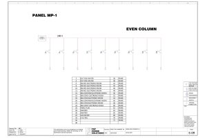
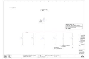
- Design of Single Line Diagrams (SLDs):
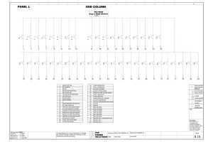
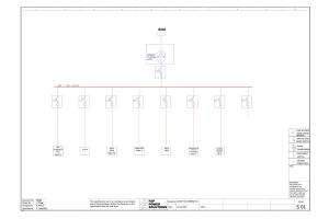
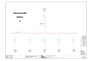
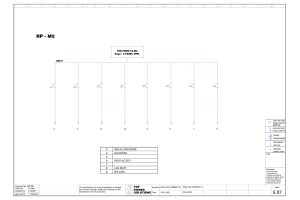
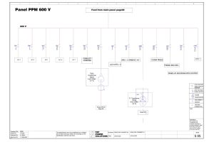
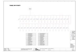
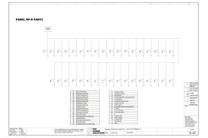
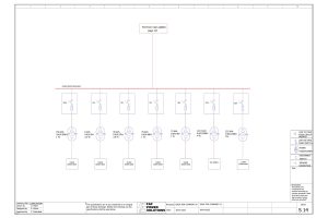
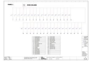
- For each of the three buildings, we created detailed Single Line Diagrams (SLDs) to represent the entire electrical distribution system. This included all the electrical panels, transformers, circuit breakers, and feeders that supply power to the machinery and lighting within the buildings.
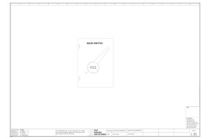
- The SLDs served as a visual representation of the power distribution network, showcasing how electricity flows from the main electrical supply to individual electrical panels, machinery, and devices.
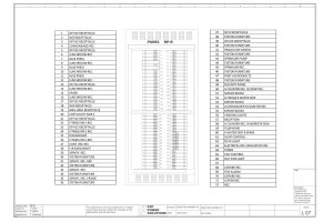
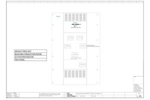
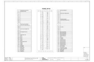
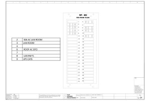
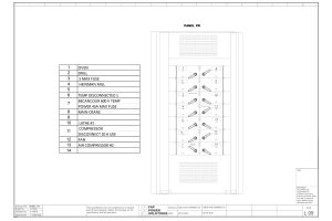
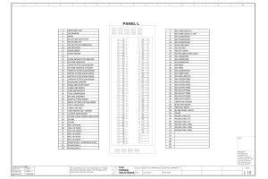
- Electrical Panel Layouts:
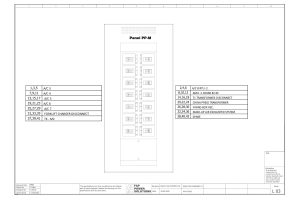
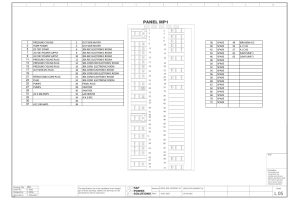
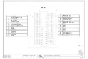
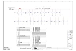
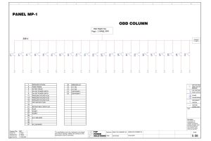
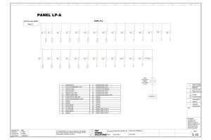
- We created comprehensive layouts for 51 electrical panels in each building. These layouts detailed the physical placement of panels, circuit breakers, switches, and other key components to ensure ease of access and compliance with safety standards.
- Panel layouts were designed for both operational efficiency and maintenance accessibility. The layout design also accounted for clear labeling of electrical components and efficient cable routing to minimize power losses and improve system reliability.
- AutoCAD Electrical:
- AutoCAD Electrical was used to draft the SLDs and panel layouts. The software allowed for precision in creating accurate diagrams and layouts, making it easier to visualize the entire electrical system. It also provided tools for automating circuit creation and reducing human error, ensuring high-quality deliverables.
- Custom symbols and libraries specific to electrical engineering standards were incorporated into the AutoCAD drawings to maintain consistency across all three buildings.
Key Challenges and Solutions:
- Complexity of the Electrical Distribution System:
- With 51 electrical panels in each of the three buildings, there was a significant amount of complexity in ensuring that all panels were properly coordinated and interconnected without overloading circuits.
- Solution: We worked closely with the electrical engineers to perform detailed load calculations, ensuring that each panel was designed to handle the required load while maintaining compliance with local electrical codes. This collaboration allowed us to create accurate SLDs that optimally distributed power throughout the facility.
- Space Constraints and Panel Placement:
- One of the challenges in creating the panel layouts was accommodating the large number of panels in the available space while maintaining clearances for safety and ease of maintenance.
- Solution: We conducted site visits and took accurate measurements of the available space in each building. The panel layouts were then carefully planned to optimize the available space while adhering to safety standards such as minimum clearance requirements for electrical panels.
- Integration with Existing Systems:
- The factory already had an existing electrical infrastructure, which meant that the new panels and systems needed to be integrated seamlessly with the older systems.
- Solution: We reviewed the existing electrical diagrams and identified integration points where new panels could be added to the existing power distribution network. This helped avoid unnecessary downtime during installation and ensured the system would operate as a cohesive whole.
Outcomes and Results:
- Accurate and Comprehensive SLDs:
- The SLDs provided a clear, easy-to-understand visual representation of the electrical system for both construction and maintenance teams. The diagrams ensured that the electrical distribution system was correctly installed and that future upgrades or troubleshooting could be easily managed.
- Efficient Electrical Panel Layouts:
- The final panel layouts optimized space usage within the buildings, ensuring that all panels were placed in compliance with safety standards. The layout also facilitated easy access for future maintenance, reducing downtime during repairs or inspections.
- Compliance with Safety Standards:
- All designs were created to comply with local electrical codes, ensuring the factory’s electrical systems were safe for operation. This included adherence to clearances, circuit protection, and panel labeling requirements.
- Improved System Reliability:
- With proper load distribution and well-planned panel placement, the factory’s electrical system was made more reliable, reducing the risk of overloads and power interruptions. This reliability contributed to the smooth operation of the manufacturing processes.
- Collaboration and Communication:
- By working closely with the electrical engineers and project management team, we were able to address any challenges proactively and ensure that the electrical systems were designed in accordance with the client’s needs. The use of AutoCAD Electrical also facilitated clear communication among stakeholders, reducing errors and misunderstandings during the design phase.

Conclusion:
This project was a successful collaboration that involved designing and drafting detailed Single Line Diagrams and electrical panel layouts for a large manufacturing facility in Mississauga. By utilizing AutoCAD Electrical and maintaining close coordination with engineers and the client, we were able to deliver a high-quality, reliable, and efficient electrical system. The project not only met the client’s needs for power distribution but also ensured long-term operational efficiency and safety for the facility.
Summery
Case Study Summary: Electrical Design for a Factory in Mississauga
Project Overview:
This project involved creating Single Line Diagrams (SLDs) and electrical panel layouts for a manufacturing facility in Mississauga, consisting of three buildings. Each building required 51 electrical panels, with designs and layouts drafted using AutoCAD Electrical.
Scope of Work:
- SLDs: Detailed power distribution diagrams showing electrical panels, transformers, and feeders.
- Panel Layouts: Designed the placement of 51 electrical panels per building, ensuring accessibility, efficiency, and safety.
- AutoCAD Electrical: Used for precision, automation, and compliance with electrical standards.
Key Challenges & Solutions:
- Complex Distribution System: Collaborated with engineers for accurate load calculations and optimized power distribution.
- Space Constraints: Measured space for efficient panel placement, ensuring safety clearance.
- Integration with Existing Systems: Seamlessly incorporated new panels into the existing infrastructure.
Results:
- Accurate SLDs and Layouts: Provided clear visual representations for installation and future maintenance.
- Compliance with Safety Standards: Ensured adherence to local codes for clearances and circuit protection.
- System Reliability: Reduced risks of overloads and power interruptions, ensuring smooth factory operations.


Conclusion:
The project successfully designed an efficient and reliable electrical distribution system for the factory, meeting all operational, safety, and regulatory requirements while improving long-term system reliability.